


www.digi.com
217
Serial Controller Module
SPI master mode
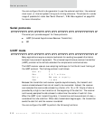
SPI master mode controls the flow of data between memory in the master SPI
interface and an external SPI slave peripheral. The SPI master determines the
number of bytes for transfer. The SPI master port simultaneously transmits and
receives the same number of bytes. A single clock signal controls the transfer of
information; for SPI master mode, the signal is an output. Information is also
qualified with an enable signal, which is controlled by the SPI master. The SPI enable
signal must be active low for data transfer to occur, regardless of the SPI clock signal.
The SPI enable function allows for multiple slaves to be addressed individually in a
multi-drop configuration.
Signals
The GEN module must be configured appropriately to allow the SPI interface signals
to interface with the PORTA and PORTC GPIO pins (see "PORTA Configuration register"
on page 74 and "PORTC Configuration register" on page 77).
Configuration
The SER module must be configured properly to operate in either master or slave
mode. For master mode operation, the MODE field in Serial Channel Control Register
B must be set to 10 before the CE field in Serial Channel Control Register A is set to 1.
Use this suggested configuration order for SPI master mode:
1 Reset the serial port by writing a 0 to Serial Channel Control Register A.
2 Configure the Serial Channel Bit-Rate register as shown:
– EBIT: 1 for enable
– TMODE: 1 for 1x mode
– RXSRC: 0 for internal
– TXSRC: 0 for internal
– RXEXT: 0 for disable
– TXEXT: either 1 or 0 — the setting has no effect
– CLKMUX: user-defined
– TXCINV: 0 for normal
– RXCINV: 0 for normal
– N: user–defined