


Serial Channel registers
246
NS7520 Hardware Reference, Rev. D 03/2006
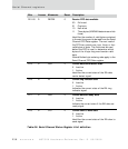
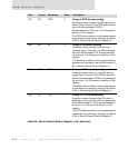
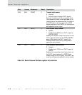
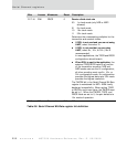
D28 R/W TXSRC 0 Transmit clock source
0 Internal
1 External (input through OUT2 signal)
Controls the source of the transmitter clock.
The transmitter clock can be provided by an
internal source, as determined by the value in
the TICS field, or by an input on the OUT2
signal attached to the PORTC pin (configured
as a special function input).
D27 R/W RXEXT 0 Drive receive clock external
0 Disable
1 Enable; drive RXCLK out OUT1 signal at
PORTA/PORTC
Enables the receiver clock to be driven on the
OUT1 signal attached to the PORTA/PORTC
ports. When using the OUT1 signal, the
PORTA/PORTC pin must be configured as
special function output.
D26 R/W TXEXT 0 Drive transmit clock external
0 Disable
1 Enable; drive TXCLK out OUT2 signal at
PORTC
Enables the transmitter clock to be driven on
the OUT2 signal attached to PORTC port.
When using the OUT2 signal, The PORTC pin
must be configured as special function output.
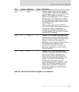
Bits Access Mnemonic Reset Description
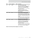
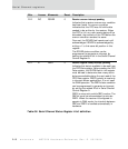
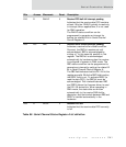
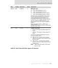
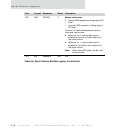
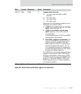
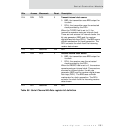
Table 90: Serial Channel Bit-Rate register bit definition