


www.digi.com
247
Serial Controller Module
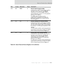
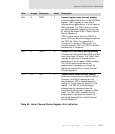
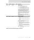
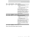
D25:24 R/W CLKMUX 0 BRG input clock
00 Input clock defined by F
XTALE
01 Input clock defined by F
SYSCLK
10 Input clock defined by input on OUT1
11 Input clock defined by input on OUT2
Controls the bit-rate generator clock source.
The bit-rate generator can use one of four
clock source: the external oscillator, the
internal PLL SYSCLK output, an input signal on
the OUT1 signal on PORTA/PORTC, or an
input signal on the OUT2 signal attached to
PORTC.
When using either OUT1 or OUT2, the
PORTA/PORTC port pin must be configured as
special function input.
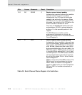
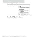
D23 R/W TXCINV 0 Transmit clock invert
0 Normal; TXD driven on falling edge of TX
clock
1 Inverted; TXD driven on rising edge of TX
clock
Controls the relationship between transmit
clock and transmit data.
When set to 0, transmit data changes
relative to the high-to-low transition of the
transmit clock.
When set to 1, transmit data changes
relative to the low-to-high transition of the
transmit clock.
Note: When using SPI mode, this bit must
be set to zero.
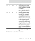
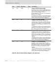
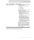
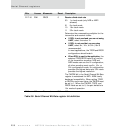
Bits Access Mnemonic Reset Description
Table 90: Serial Channel Bit-Rate register bit definition