


www.digi.com
225
Serial Controller Module
Serial Channel registers
All control bits are active high unless followed by an underscore (_); the underscore
indicates active low.
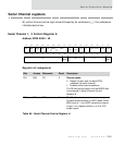
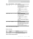
Serial Channel 1, 2 Control Register A
Address: FFD0 0000 / 40
Register bit assignment
Bits Access Mnemonic Reset Description
D31 R/W CE 0 Channel enable
0 Resets the port and the data FIFOs
(disables the serial channel)
1 Enables serial channel operation
The CE field cannot be set until the MODE field
is configured in Serial Channel Control
Register B.
D30 R/W BRK 0 Send break
Forces a break condition in UART mode. While
BRK is set to 1, the UART transmitter outputs
a logic 0 or a space condition, on the TXD
output signal.
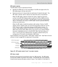
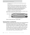
Table 85: Serial Channel Control Register A
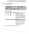
13121110987654321015 14
31 29 28 27 26 25 24 23 22 21 20 19 18 17 1630
EPS WLS
DTR
CE
IE IE
BRK
STICK
P
PE STOP
CTS
TX
RTS
RX
RL LL OUT1/OUT2 RTS
ERX
DMA
IE
ETX
DMA