


www.digi.com
73
GEN Module
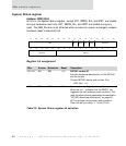
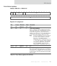
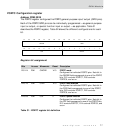
Timer Status registers
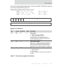
Address: FFB0 0014 / FFB0 001C
Register bit assignment
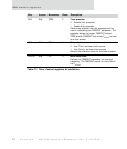
Bits Access Mnemonic Reset Description
D31 N/A Reserved N/A N/A
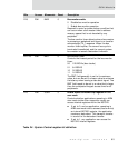
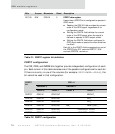
D30 R/C TIP 0 Timer interrupt pending
Set to 1 when the timer is enabled and the CTC
value counts down to 0. TIP generates an interrupt
to the CPU if the TIE bit in the Timer Control
register is set. Writing a 1 to the same bit position
in the Timer Status register clears the TIP bit.
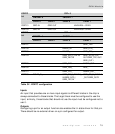
Note: TIP is set immediately when the TE bit (in
the Timer Control register) is changed
from 0 to 1. An interrupt occurs
immediately after TE transitions from 0 to
1. If this initial interrupt causes a problem
in any specific application, the software
must be designed to ignore the first
interrupt after TE transitions from 0 to 1.
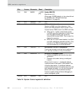
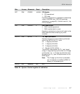
D29:27 N/A Reserved N/A N/A
D26:00 R CTC O Current timer count
Each time the CTC field reaches zero, the TIP bit is
set and the CTC is reloaded with the value defined
in the ITC field. The CTC continues to count back
down to zero.
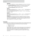
Table 28: Timer Status registers bit definition
13121110987654321015 14
31 29 28 27 26 25 24 23 22 21 20 19 18 17 1630
Rsvd TIP Reserved TCLK CTC
CTC