


www.digi.com
99
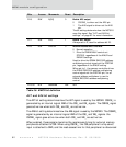
Memory Controller Module
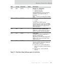
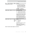
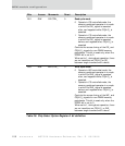
WAIT[3:0]/BCYC[1:0] continued
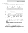
The first memory cycle of a burst
access follows the timing of a single
access. CAS_ is asserted BCYC BCLK
cycles for all cycles that follow the
initial cycle in a burst. If BCYC is set to
0, the controller cannot execute burst
cycles.
When DRSEL=1 and DMODE=10
See "SDRAM," beginning on page 111.
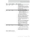
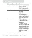
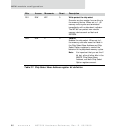
D05:04 R/W BSIZE 0 Burst access size in beats
00 2 system bus cycles in burst access
01 4 system bus cycles in burst access
10 8 system bus cycles in burst access
11 16 system bus cycles in burst access
Controls the maximum number of memory
cycles that can occur in a burst cycle. This
field determines only the maximum number
of allowable bus cycles; the current bus
master can choose to burst a smaller
amount. If the current bus master continues
to burst, the peripheral terminates the burst
when the number of memory cycles reaches
the maximum allowed by this field.
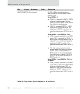
D03:02 R/W PS 0 for
CS[4:1],
per boot-
strap for
CS0
Port size
00 32-bit port size
01 16-bit port size
10 8-bit port size
11 Reserved
Controls the size of the memory peripheral
device: 8-, 16-, or 32-bits.
The initial state of PS for CS0 depends on
hardware initialization settings. See
"NS7520 bootstrap initialization" on page
60 for more information.
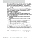
Bits Access Mnemonic Reset Description
Table 38: Chip Select Option Register A bit definition