


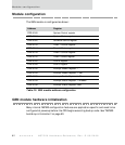

GEN module registers
70
NS7520 Hardware Reference, Rev. D 03/2006
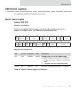
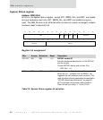
Software Service register
Address: FFB0 000C
The Software Service register (SWSR) acknowledges the system watchdog timer. To
do so, firmware must write
‘h5A and ‘hA5 to the register using two separate write
operations. There is no restriction on the time between the two operations, but the
operations must occur in the proper sequence with the proper data values.
The Software Service register can request a software reset of the NS7520 hardware.
Firmware must write
‘h123 and ‘h321 to the register using two separate write
operations. There is no restriction on the time between the two operations, and the
two operations must occur in the proper sequence with the proper data values. The
processor must be in supervisor mode for the second operation.
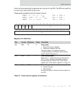
Register bit assignment
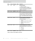
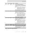
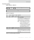
Timer Control registers
Address: FFB0 0010 / FFB0 0018
Timers 1 and 2 provide the CPU with programmable interval timer(s). The timers use
the F
XTALE
timing reference and an optional 9-bit prescaler or the system clock. Each
timer provides a 27-bit programmable-down counter mechanism.
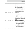
The CPU loads an initial count register (ITC) to define the timeout period. When the
current counter decrements to zero, the counter is reloaded. The reloading of the
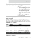
Bits Access Mnemonic Reset Description
D31:00 W SWSR 0 Software Service register
Table 26: Software Service register bit definition
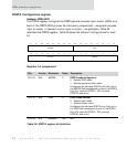
13121110987654321015 14
31 29 28 27 26 25 24 23 22 21 20 19 18 17 1630
SWSR
SWSR