


Interrupts
80
NS7520 Hardware Reference, Rev. D 03/2006
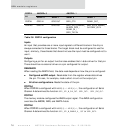
READBACK
When reading the CDATA field, the data read depends on how the pin is configured:
Configured as GPIO output. Reads data from the register whose data drives
the pin. This can, for example, mask a short circuit on the output pin.
All other configurations. Reads the state of the pin.
PORTC4
When PORTC is configured with
CSF[4]=1:CMODE[4]=1:CDIR[4]=1, the configuration of
Serial Channel B determines the function
SER2_SPI_M_CLK_OUT, SER2_TXC_OUT,or
SER2_OUT1. Following external reset, CSF[4]=0:CMODE[4]=1:CDIR[4]=1; that is, set to
drive RESET_ output.
PORTC0
When PORTC0 is configured with
CSF[0]=1:CMODE[0]=1:CDIR[0]=1, the configuration of
Serial Channel B determines the function
SER2_SPI_M_ENABLE_OUT or SER2_OUT2.
PORTC[3:0]
These pins can be programmed individually to generate level-sensitive interrupts.
Level-sensitive interrupts generate an interrupt when the input signal matches the
state of the corresponding DIR bit. The interrupt condition persists until the input
signal changes state or the configuration is changed.
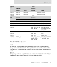
Interrupts
There are two wires that go to the CPU core and interrupt the processor:
IRQ. Normal interrupt.
FIRQ. Fast interrupt.
FIRQ has higher priority than IRQ, providing a simple two-tier priority scheme to the
interrupt system. Most sources of interrupts on the NS7520 come from the IRQ line.
FIRQ interrupt sources are the three built-in timers and the watchdog timer,
controlled by the Timer 1/2 and Status registers and the System Control register,
respectively.