


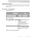

Serial Channel registers
226
NS7520 Hardware Reference, Rev. D 03/2006
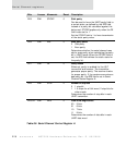
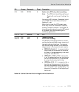
D29 R/W STICKP 0 Stick parity
Can be used to force the UART parity field to
a certain state, as defined by the EPS field,
instead of a parity bit calculated against the
data word. STICKP applies only when the PE
field is also set to 1.
Set the STICKP field to 1 to force transmission
of the static parity value.
D28 R/W EPS 0 Even parity select
0 Odd parity
1 Even parity
Determines whether the serial channel uses
odd or even parity when calculating the parity
bit in UART mode. When the STICKP field is
set, the EPS field defines the static state for
the parity bit.
D27 R/W PE 0 Parity enable
When set, parity is enabled for the UAT
transmitter and receiver. The transmitter
generates proper parity. The receiver checks
for proper parity. If the receiver encounters a
bad parity bit, the RPE field is set in Serial
Channel Status Register A.
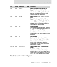
D26 R/W STOP 0 Number of stop bits
0 1 stop bit
1 1.5 stops for a 5-bit word, 2 stop bits for
other words.
Determines the number of stop bits in each
UART transmitter.
D25:24 R/W WLS 0 Data word length select
00 5 bits
01 6 bits
10 7 bits
11 8 bits
Determines the number of data bits in each
UART data word.
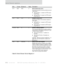
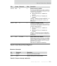
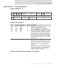
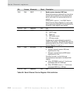
Bits Access Mnemonic Reset Description
Table 85: Serial Channel Control Register A