


www.digi.com
137
DMA Module
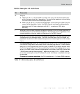
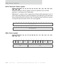
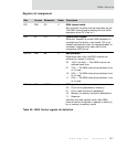
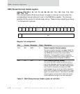
Register bit assignment
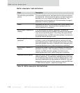
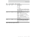
Bits Access Mnemonic Reset Description
D31 R/W CE 0 DMA channel enable
Set only after the other channel mode bits are set.
The DMA channel begins reading the first buffer
descriptor when CE is set to 1.
D30 W CA 0 Channel abort request
When set, causes the current DMA operation to
complete and the buffer to be closed. CA is not
cleared automatically after the requested abort is
complete; firmware must clear the bit after
recognizing CAIP active.
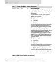
D29:28 R/W BB 0 Bus bandwidth
Determines how often the DMA channel can
arbitrate for access to the bus.
00 100% (no limit) — The DMA channel can
arbitrate each time.
01 75% — The DMA channel can arbitrate 3 out
of 4 times.
10 50% — The DMA channel can arbitrate 2 out
of 4 times.
11 25% — The DMA channel can arbitrate 1 out
of 4 times.
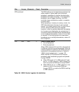
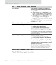
D27:26 R/W MODE 0 DMA operation mode
00 Fly-by write (peripheral-to-memory)
01 Fly-by read (memory-to-peripheral)
10 Memory-to-memory (source-to-destination)
11 Reserved
Identifies the data transfer mode. Each DMA
channel can be configured to operate in either fly-
by or memory-to-memory mode.
Table 50: DMA Control register bit definition