


SPI mode
214
NS7520 Hardware Reference, Rev. D 03/2006
Information transfer is also qualified with an enable signal. The SPI enable
signal must be active low for data transfer to occur, regardless of the SPI
clock signal. The SPI enable function allows multiple slaves to be
individually addressed in a multi-drop configuration.
Note:
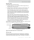
The NS7520 supports only SPI modes 0 and 1. See Figure 25, "SPI master
mode 0 and 1 two-byte transfer," on page 219 and Figure 26, "SPI slave
mode 0 and 1 two-byte transfer," on page 222 for illustrations.
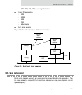
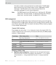
FIFO management
Data flow between the SPI master/slave interfaces and memory occurs through the
FIFO blocks within the SER module. Each serial port provides a 32-byte transmit FIFO
and a 32-byte receive FIFO. Both the transmit and receive FIFOs are memory-mapped
to the processor address space.
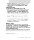
Transmit FIFO interface
The processor can write either 1, 2, or 4 bytes at a time to the transmit FIFO. The
number of bytes written is controlled by the data size defined by the ARM processor
as shown in these examples:
Operating in Endian modes
Big Endian mode configuration. Transmits first the most significant bytes in
the word written to the FIFO. For example, the long word
0x11223344 results
in the character
0x11 being transmitted first and 0x44 being transmitted
last.
Terminology What’s being written Value
C Byte using a byte pointer
(char*)0xffd00010=(char)data
C 2 bytes using a short pointer
(short)0xffd00010=(short)data
C 4 bytes using a standard long word
pointer
(long)0xffd00010=(long)data
Assembler Byte STRB instructions
Assembler Half word STRH instructions
Assembler Long word STR instructions