


EFE configuration
162
NS7520 Hardware Reference, Rev. D 03/2006
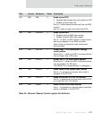
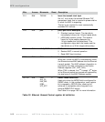
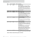
D11 R/W TXCINV 0 Invert the transmit clock input
Set to 1 only when the external Ethernet PHY
generates a clock that is inverted in phase relative
to what the MAC is expecting.
This bit is not required for most commercially
available PHY devices.
D10 R/W pNA 0 pSOS pNA buffer descriptors
0 Standard receiver format. The data block
immediately follows the 14-byte header block.
1 pSOS pNA receiver format. The receiver
inserts a 2-byte padding between the
14-byte header and the data block. This
configuration aligns both the header and the
data blocks on a 32-bit longword boundary.
D09 R/W MAC_RESET 0 MAC software reset
0 Restore MAC to normal operation
1 Reset MAC host interface
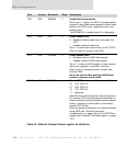
D08 R/W ITXA 0 Insert transmit source address
When set, forces the MAC to automatically insert
the Ethernet source MAC address into the Ethernet
transmit packet. The MAC address information is
provided by the data configured in the Station
Address registers (SA1, SA2, SA3).
When ITXA is cleared, the 7
th
through 12
th
bytes
in the Ethernet packet are ignored and replaced by
the size bytes in the MAC Address register.
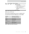
D07:02 R/W PDN:
AUI_TP:
LNK_DIS:
LPBK:
UTP_STP
0 ENDEC media control bits
Used only when the MODE field is configured for
ENDEC mode. In this configuration, each register
bit is mapped to NS7520 pins, allowing the
software to manipulate control signals on an
external ENDEC PHY device.
See Table 54 on page 163 for more information.
Bits Access Mnemonic Reset Description
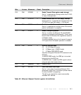
Table 53: Ethernet General Control register bit definition