


www.digi.com
19
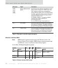
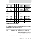
Pinout and Packaging
Signal descriptions
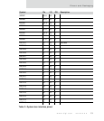
The Ethernet MII (media independent interface) provides the connection between the
Ethernet PHY and the MAC (media access controller).
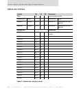
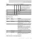
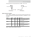
TXD3 GP output A12 O 2 TX data 3 State of AUI_TP[0] bit
TXD2 GP output B11 O 2 TX data 2 State of AUI_TP[1] bit
TXD1 GP output D11 O 2 TX data 1 Inverted state of PDN
bit, open collector
TXD0 TXD A11 O 2 TX data 0 Transmit data
TXER GP output A13 O 2 TX code error State of LNK_DIS_ bit
TXEN B12 O 2 TX enable
TXCOL A14 I Collision
RXCRS D12 I Carrier sense
RXCLK C12 I RX clock
RXD3 GP input D14 I RX data 3 Read state in bit 12
RXD2 GP input B15 I RX data 2 Read state in bit 15
RXD1 GP input A15 I RX data 1 Read state in bit 13
RXD0 RXD B13 I RX data 0 Receive data
RXER GP input C15 I RX error Read state in bit 11
RXDV GP input D15 I RX data valid Read state in bit 10
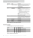
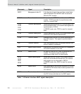
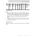
Mnemonic Signal Description
MDC MII management clock Provides the clock for the MDIO serial data
channel. The MDC signal is an NS7520 output.
The frequency is derived from the system
operating frequency per the CLKS field setting (see
the CLKS field in Table 69: "MII Management
Configuration register bit definition" on page 191).
Table 7: Ethernet interface MAC signal description
Symbol Pin I/O OD Description
Table 6: Ethernet interface MAC pinout