


www.digi.com
5
About the NS7520
NS7520 module block diagram
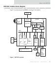
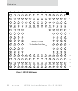
Figure 1 is an overview of the NS7520, including all the modules.
Figure 1: NS7520 overview
Debugger
PLL
System
Clock
JTAG Debug
Interface
ARM7TDMI
FIRQ
IRQ
2 timers
Watchdog
timer
Power
3.3V
1.5V
BBUS
D
M
A
D
M
A
D
M
A
D
M
A
Serial-A
UART
SPI
Serial-B
UART
SPI
4
level
interrupt
inputs
16 GPIO
Ethernet
controller
802.3
compliant
External
memory
controller
NS7520
Reset
Address bus
Serial transceivers and other
devices
MII
Memory
devices
Flash
SRAM
FP DRAM
SDRAM
Boot
config