


www.digi.com
251
Serial Controller Module
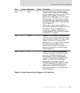
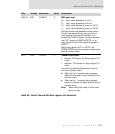
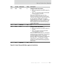
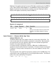
D14 R/W TICS 0 Transmit internal clock source
0 BRG; the transmitter uses BRG output for
its clock
1 DPLL; the transmitter uses the extracted
clock provided by the DPLL.
When the TXSRC field is set to 0, the
transmitter operates using an internal clock.
There are two sources for internal clocks: the
bit-rate generator (BRG) and the receiver
digital phase lock loop (DPLL). The BRG uses a
divider mechanism for clock generation. The
DPLL extracts the clock from the incoming
receive data stream.
D13 N/A Reserved N/A N/A
D12 R/W RICS 0 Receiver internal clock source
0 BRG; the transmitter uses BRG output for
its clock
1 DPLL; the receiver uses the extracted
clock provided by the DPLL.
When the RXSRC field is set to 0, the receiver
operates using an internal clock. There are two
sources for internal clocks: the bit-rate
generator (BRG) and the receiver digital phase
lock loop (DPLL). The BRG uses a divider
mechanism for clock generation. The DPLL
extracts the clock from the incoming receive
data stream.
D11 N/A Reserved N/A N/A
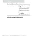
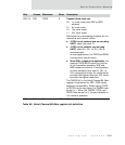
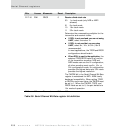
Bits Access Mnemonic Reset Description
Table 90: Serial Channel Bit-Rate register bit definition