


www.digi.com
213
Serial Controller Module
Enable the transmitter using the CTS handshaking signal. In this mode,
the transmitter cannot start a new UART data frame unless CTS is active. If
CTS is dropped anywhere in the middle of a UART data frame, the current
character is completed but the next character is stalled.
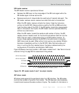
Signal its receiver FIFO status using the RTS handshaking signal. When
the receive FIFO has only four characters of available space, the RTS signal
is dropped. The RTS and CTS pairs can be used for hardware flow control.
Operate in synchronous timing mode. When using synchronous timing
mode, a clock is provided with each bit; an over-sampling technique is not
required. Transmit and receive clocks must be connected between two end
points.
See "General-purpose I/O configurations" on page 222 and "Serial Channel registers"
on page 225 for information about signals and configuration.
SPI mode
The SPI (serial peripheral interface) controller provides:
Full-duplex, synchronous interface. The master interface operates in a
broadcast mode, activating the slave interface with the select (SEL_) signal.
The master interface can also be configured to address more than one slave
interface using GPIO pins.
Four-wire connection (TXD, RXD, CLK, SEL_). The transmitter and
receiver use the same clock. When configured in master mode, the
channel’s bit-rate generator provides the timing reference.
Character-oriented data channel. The protocol can provide simple
parallel/serial data conversion to stream serial data between memory and a
peripheral.
Master and slave configurations. The SPI port is capable of simultaneous
full-duplex operation. The transfer of information is controlled by a single
clock signal.
– For the SPI master interface, the clock signal is an output.
– For the SPI slave interface, the clock signal is an input.