


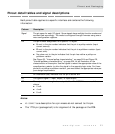
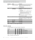

Pinout detail tables and signal descriptions
12
NS7520 Hardware Reference, Rev. D 03/2006
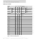
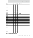
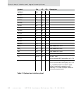
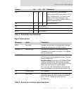
System bus interface
Symbol Pin I/O OD Description
BCLK A6 O 8 Synchronous bus clock
External bus Other External bus Other
ADDR27 CS0OE_ N10 U I/O 4 Addr bit 27 Logical AND of CS0_
and OE_
ADDR26 CS0WE_ P10 U I/O 4 Addr bit 26 Logical AND of CS0_
and WE_
External bus External bus
ADDR25 M10 U I/O 4 Remainder of address bus (through
ADDR0)
ADDR24 R10 U I/O 4
ADDR23 N9 U I/O 4
ADDR22 R9 U I/O 4
ADDR21 M9 U I/O 4
ADDR20 N8 U I/O 4
ADDR19 P8 U I/O 4
ADDR18 M7 U I/O 4
ADDR17 R7U I/O 4
ADDR16 N7 U I/O 4
ADDR15 R6 U I/O 4
ADDR14 M6 U I/O 4
ADDR13 P6 U I/O 4
ADDR12 N6 U I/O 4
ADDR11 M5 U I/O 4
ADDR10 P5 U I/O 4
ADDR9 N5 U I/O 4
ADDR8 R4 U I/O 4
Table 2: System bus interface pinout