


www.digi.com
79
GEN Module
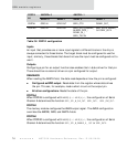
Inputs
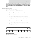
An input that provides one or more input signals to different blocks in the chip is
always connected to those blocks. The target block must be configured to use the
input; similarly, those blocks that should not use the input must be configured not to
use it.
Outputs
Configuring a pin for an output function also enables the tri-state driver for that pin.
There should be no external driver on a pin configured for output.
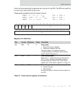
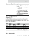
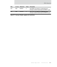
PORTC1 GPIO IN GPIO OUT LEVELIRQ1=CDIR1
PORTC0 GPIO IN GPIO OUT LEVELIRQ0=CDIR0
PORTC
bit
CSF=1
CMODE=0 CMODE=1
CDIR=0 CDIR=1 CDIR=0 CDIR=1
PORTC7 SER2_TXD
PORTC6 DREQ2_IN SER2_DTR_
PORTC5 REJECT_ SER2_RTS_
PORTC4 SER2_SPI_S_CLK IN/
SER2_RXC IN
SER2_SPI_M_CLK
OUT/SER2_TXC OUT/
SER2_OUT1
PORTC3 SER2_RXD DACK2_OUT
PORTC2 SER2_DSR_ RPSF_
PORTC1 SER2_CTS_ DONE2_OUT_
PORTC0 DONE2_IN_ SER2_SPI_S_ENABLE_
IN/SER2_DCD_/
SER2_TXC IN
SER2_SPI_M_ENABLE
_OUT/SER2_OUT2
PORTC
bit
CSF=0
CMODE=0 CMODE=1
CDIR=0 CDIR=1 CDIR=0 CDIR=1
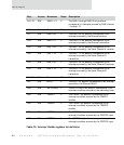
Table 32: PORTC configuration