


www.digi.com
23
Pinout and Packaging
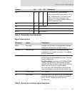
Notes:
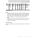
1 RESET output indicates the reset state of the NS7520. PORTC4 persists beyond
the negation of RESET_ for approximately 512 clock cycles if the PLL is disabled.
When the PLL is enabled, PORTC4 persists beyond the negation of RESET_ to
allow for PLL lock for 100 microseconds times the ratio of the VCO to XTALA.
Note that this GPIO is left in output mode active following a hardware
RESET.
2 *PORTC[3:0] pins provide level-sensitive interrupts. The inputs do not need to
be synchronous to any clock. The interrupt remains active until cleared by a
change in the input signal level.
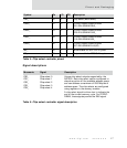
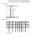
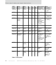
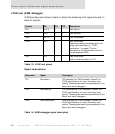
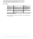
Signal descriptions
See Chapter 6, "GEN Module," for signal and configuration information for PORTA and
PORTC.
PORTC0
2
TXCB/
OUT2B_/
DCDB_
LIRQ0/
DONE2_(I)
E14 U I/O 2 Pgm’able Out/
Channel 2
DCD/Channel 2
SPI enable
(SEL_)/Channel
2 TXCLK
Level sensitive
IRQ/DMA
channel 4/6
DONE_in
GPIO
signal
Serial
signal
Other
signal
Pin I/O OD
Serial channel
description
Other
description
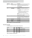
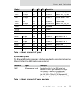
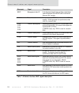
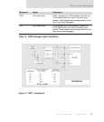
Table 9: GPIO pinout