


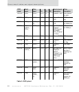

Pinout detail tables and signal descriptions
26
NS7520 Hardware Reference, Rev. D 03/2006
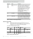
JTAG test (ARM debugger)
JTAG boundary scan allows a tester to check the soldering of all signal pins and tri-
state all outputs.
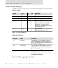
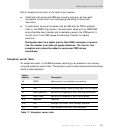
Signal descriptions
Symbol Pin I/O OD Description
TDI N14 U I Test data in
TDO M13 O 2 Test data out
TMS M12 U I Test mode select
TRST_ M14 I Test mode reset
Requires external termination when not
being used (see Figure 4, "TRST_
termination," on page 27 for an
illustration of the termination circuit on
the development PCB).
TCK P15 I Test mode clock
Add an external pullup to 3.3V.
Table 13: JTAG test pinout
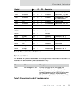
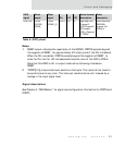
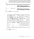
Mnemonic Signal Description
TDI Test data in TDI operates the JTAG standard. Consult the
JTAG specifications for use in boundary-scan
testing. These signals meet the requirements of the
Raven and Jeeni debuggers.
TDO Test data out TDO operates the JTAG standard. Consult the
JTAG specifications for use in boundary-scan
testing. These signals meet the requirements of the
Raven and Jeeni debuggers.
TMS Test mode select TMS operates the JTAG standard. Consult the
JTAG specifications for use in boundary-scan
testing. These signals meet the requirements of the
Raven and Jeeni debuggers.
Table 14: ARM debugger signal description