


www.digi.com
231
Serial Controller Module
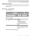
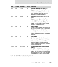
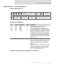
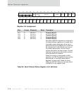
Serial Channel 1, 2 Control Register B
Address: FFD0 0004 / 44
Register bit assignment
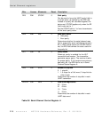
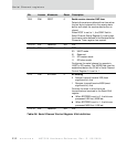
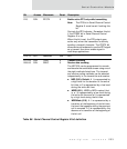
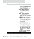
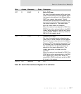
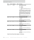
Bit Access Mnemonic Reset Description
D31
D30
D29
D28
R/W
R/W
R/W
R/W
RDM1
RDM2
RDM3
RDM4
0
0
0
0
Enable receive data match 1/2/3/4
When the serial channel is configured to
operate in UART mode, the RDM bits enable
the receive data match comparators. A receive
data match comparison detection can be used
to close the current receive buffer descriptor.
The last byte in the current receive data buffer
contains the match character. Each of these
bits enables the respective byte in the Receive
Match register.
D27 R/W RBGT 0 Enable receive buffer GAP timer
Detects the maximum allowed time from when
the first byte is placed into the receive data
buffer and when the receive data buffer is
closed.
When RBGT is set to 1, the BGAP field in Serial
Channel Status Register A is set when the
timeout value defined in the Receive Buffer
GAP Timer register has expired.
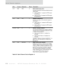
Table 88: Serial Channel Control Register B bit definition
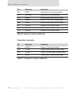
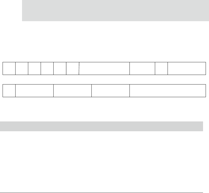
13121110987654321015 14
31 29 28 27 26 25 24 23 22 21 20 19 18 17 1630
RDM4RDM1
RTS
TX
RDM2 RDM3 RBGT RCGT Reserved MODE
BIT
ORDR
Reserved TENC RDEC
Reserved
Reserved