


www.digi.com
163
Ethernet Module
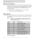
ENDEC mode and NS7520 pins
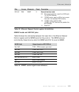
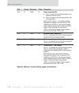
Table 54 shows the relationship between the lower bits in the Ethernet General
Control register and the NS7520 pins that they control. The NS7520 pins are
controlled by these bits only when the MODE field (D15:14) is set to ENDEC.
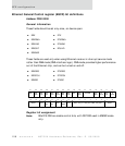
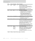
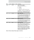
D01:00 R/W EXINT 0 External interface mode
00 MII normal operation, used for all MII-style
10/100 PHY devices
01 TP-PMD mode, used for PHYs that contain
their own non-standard PCS circuitry
10 10 Mbit mode, used for older
10-Mbit-only PHY devices that predate the
MII standard.
11 Reserved
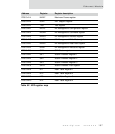
MODE field Output based on EFE CSR bit
Not ‘b00 TXD1=PDN inverted, open drain
Not ‘b00 TXD2=AUI_TP[1]
Not ‘b00 TXD3=AUI_TP[0]
Not ‘b00 TXER=LNK_DIS_
Not ‘b00 and not ‘b11 MDC=LPBK
‘b11 MDC=LPBK inverted
Not ‘b00 MDO=UTP_STP
Table 54: ENDEC control signal cross-reference
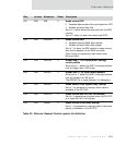
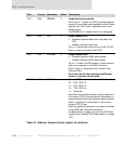
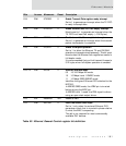
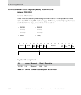
Bits Access Mnemonic Reset Description
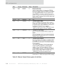
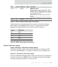
Table 53: Ethernet General Control register bit definition