


www.digi.com
11
Pinout and Packaging
Pinout detail tables and signal descriptions
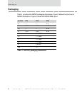
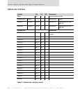
Each pinout table applies to a specific interface and contains the following
information:
Notes:
NO CONNECT as a description for a pin means do not connect to this pin.
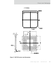
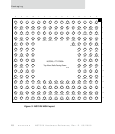
The 177th pin (package ball) is for alignment of the package on the PCB.
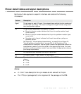
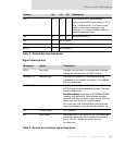
Column Description
Signal The pin name for each I/O signal. Some signals have multiple function modes and
are identified accordingly. The mode is configured through firmware using one or
more configuration registers.
Pin The pin number assignment for a specific I/O signal.
U next to the pin number indicates that the pin is a pullup resistor (input
current source).
D next to the pin number indicates that the pin is a pulldown resistor (input
current sink).
No value next to the pin indicates that the pin has neither a pullup nor
pulldown resistor.
See Figure 28, "Internal pullup characteristics," on page 264 and Figure 29,
"Internal pulldown characteristics," on page 264 for an illustration of the
characteristics of these pins. Use the figures to select the appropriate value of the
complimentary resistor to drive the signal to the opposite logic state. For those
pins with no pullup or pulldown resistor, you must select the appropriate value per
your design requirements.
_ An underscore (bar) indicates that the pin is active low.
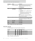
I/O The type of signal — input, output, or input/output.
OD The output drive strength of an output buffer. The NS7520 uses one of three
drivers:
2 mA
4 mA
8 mA