


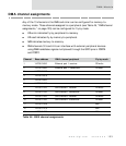
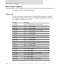
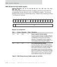

DMA channel registers
138
NS7520 Hardware Reference, Rev. D 03/2006
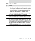
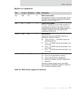
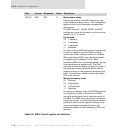
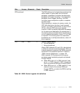
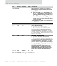
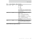
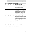
D25:24 R/W BTE 0 Burst transfer enable
Determines whether the DMA channel can use
burst transfers through the bus. This configuration
applies to both buffer descriptor and peripheral
data access.
For DMA channel 1, the BB, MODE, and BTE
configuration must be the same in all four control
registers (A, B, C, and D).
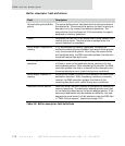
Fly-by mode:
00 1 operand
01 2 operands
10 4 operands
11 Reserved
In fly-by mode, the BTE field controls the maximum
number of operands that the DMA controller
moves each time it acquires control of the BBus.
When performing DMA to an internal peripheral,
the operand size is always 32 bits. When
performing DMA to an external peripheral, the size
field determines the operand size. The DMA
controller moves information using burst cycles. If
the attached memory peripheral device cannot
support bursting or the peripheral terminates the
burst, the maximum number of bytes defined by
BTE is not reached.
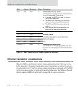
Memory-to-memory mode:
00 No burst
01 8-byte burst
10 16-byte burst
11 Reserved
In memory-to-memory mode, the BTE field controls
the maximum number of bytes that the DMA
controller moves each time it acquires control of
the BBus. The DMA controller moves information
using burst cycles. If the attached source memory
peripheral device cannot support bursting or the
source peripheral terminates the burst, the
maximum number of bytes defined by BTE is not
reached.
Bits Access Mnemonic Reset Description
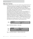
Table 50: DMA Control register bit definition