


www.digi.com
75
GEN Module
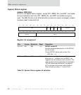
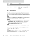
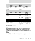
PORTA Configuration
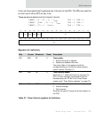
The ADIR and AMODE bits together provide independent configuration of each pin.
Each column in this table denotes one of the possible configurations for each bit. If
there is no entry in one of the columns (for example,
PORTA7>AMODE=1>ADIR=0), the bit
cannot be used in that configuration.
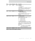
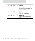
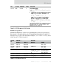
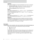
D07:00 R/W ADATA 0 PORTA data register
Used when a PORTA bit is configured to operate in
GPIO mode.
Reading the ADATA field provides the current
state of the GPIO signal, regardless of its
configuration mode.
Writing the ADATA field defines the current
state of the GPIO signal when the signal is
defined to operate in GPIO output mode.
Writing the ADATA field when configured in
GPIO input mode or special function mode has
no effect.
Each bit in the ADATA field corresponds to one of
the PORTA bits; D07 controls PORTA7, D06
controls PORTA6, and so on.
PORTA
bit
AMODE=0 AMODE=1
ADIR=0 ADIR=1 ADIR=0 ADIR=1
PORTA7 GPIO IN GPIO OUT SER1_TXD
PORTA6 GPIO IN GPIO OUT DREQ1_IN SER1_DTR_
PORTA5 GPIO IN GPIO OUT SER1_RTS_
PORTA4 GPIO IN GPIO OUT SER1_RI_/SER1_RXC
IN/SER1_SPI_S_CLK
IN
SER1_SPI_M_CLK
OUT/SER1_OUT1/
SER1_RXC OUT
PORTA3 GPIO IN GPIO OUT SER1_RXD DACK1_OUT
PORTA2 GPIO IN GPIO OUT SER1_DSR_ AMUX
Table 30: PORTA configuration
Bits Access Mnemonic Reset Description
Table 29: PORTA register bit definition