


Static memory (SRAM) controller
104
NS7520 Hardware Reference, Rev. D 03/2006
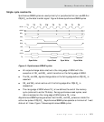
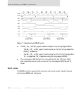
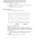
Figure 7: Asynchronous SRAM cycles
The BE_, OE_, and WE_ signals transition based on the falling edge of BCLK.
– The BE_, OE_, or WE_ signal transitions low on the first falling edge after
CS[4:0]_ is asserted.
– The BE_, OE_, or WE_ signal transitions high on the first falling edge after
TA_ is recognized (TA_ is sampled using the rising edge of BCLK).
The rising edge of BCLK where TA_ is low defines the last TW cycle. Read
data is sampled and write data is valid on the rising edge of BCLK where TA_
is low.
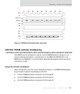
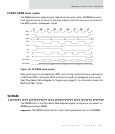
Burst cycles
The SRAM controller supports both read and write burst cycles. Figure 8 shows a
synchronous SRAM burst read cycle.
T1 T2 T1 TW TW T2 T1 TW T2
Async Write Async Read Async Write
TW
***
BCLK
ADDR
BEn_
CS0_
CS1_
R/W_
WE_
OE_
DATA
TA_