


www.digi.com
139
DMA Module
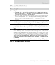
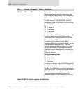
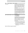
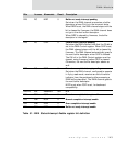
BTE continued The DMA delivers to the destination peripheral the
same number of bytes read from the source
peripheral, regardless of whether the destination
peripheral can support bursting. If the destination
peripheral cannot support bursting, the DMA
controller issues multiple bus cycles to complete
the data move.
When operating in memory-to-memory mode, the
SIZE field determines the size of each operand
moved. It is usually more efficient to use a size of
32 bits; different SIZE values are required,
however, when the address alignment boundaries
for the source and destination are mismatched. If
the starting source and destination boundaries are
not on longword boundaries, a size of 16 or 8 bits
is required. If the starting source or destination
boundaries are on odd-byte boundaries, a size of 8
bits is required.
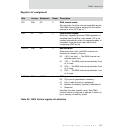
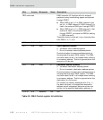
D23 R/W REQ 0 Channel request source
0 Internal peripheral
1 External peripheral
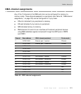
Allows DMA channels 3/5 and 4/6 to be attached
to either an internal or external peripheral. When an
internal peripheral is selected, the DMA channel is
hardwired to the peripheral defined in Table 49,
“DMA channel assignments,” on page 133.
DMA channels 3/5 interface with an external
peripheral using handshaking signals multiplexed
through PORTA.
When REQ is set to 0 in DMA channel 3 and
set to 1 in DMA channel 5, DMA channel 5 is
tied to the external DMA port through PORTA.
When REQ is set to 1 in DMA channel 3, that
channel is tied to the external DMA port
through PORTA, no matter the REQ bit setting
in DMA channel 5.
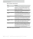
Bits Access Mnemonic Reset Description
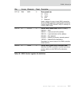
Table 50: DMA Control register bit definition