


DMA channel registers
142
NS7520 Hardware Reference, Rev. D 03/2006
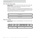
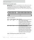
DMA Status/Interrupt Enable register
Address: FF90 0014 / 34 / 54 / 74 / 94 / B4 / D4 / F4 / 114 / 134 / 154 / 174 / 194 /
1B4 / 1D4 / 1F4
The interrupt enable (IE) bits can be set to cause an interrupt to occur when the
corresponding interrupt status bit is set in the DMA Status register. The interrupt
pending (IP) bits are set to indicate begin active. These bits are cleared by writing a
1 to the same bit locations.
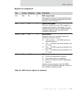
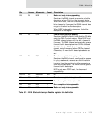
Register bit assignment
Bits Access Mnemonic Reset Description
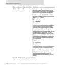
D31 R/C NCIP 0 Normal completion interrupt pending
Set when a buffer descriptor has been closed (for
normal conditions) and either the NCIE bit is set or
the IDONE bit is active in the current buffer
descriptor. A normal DMA channel completion
occurs when the BLEN count expires (gets to 0) or
when a peripheral device signals completion.
D30 R/C ECIP 0 Error completion interrupt pending
Set when the DMA channel encounters either a
bad buffer descriptor pointer or a bad data buffer
pointer. When ECIP is set, the DMA channel stops
until the bit is cleared by firmware; the DMA
channel does not go to the next buffer descriptor.
When ECIP is cleared, the buffer descriptor is tried
again from where it left off. The CA bit in the DMA
Control register can be used to abort the current
buffer descriptor and go to the next descriptor.
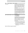
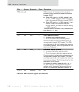
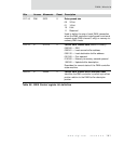
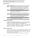
Table 51: DMA Status/Interrupt Enable register bit definition
13121110987654321015 14
31 29 28 27 26 25 24 23 22 21 20 19 18 17 1630
NRIP NCIE NRIENCIP
BLEN
ECIP
ECIE
CAIECAIP PCIP Reserved
PCIE
WRAP
IDONE
LAST
FULL
Rsvd