


SDRAM
122
NS7520 Hardware Reference, Rev. D 03/2006
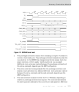
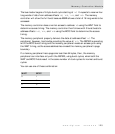
wait states are inserted after the read command, depending on the value of
the BCYC configuration. The BCYC configuration identifies the CAS latency
specification for the SDRAM.
The burst stop command is issued at the end of the current burst read
operation. The SDRAM continues to burst read data for an additional
number of BCLK cycles after the burst stop command is issued. The number
of cycles is calculated as
CAS latency - 1. When the CAS latency value is
greater than one, additional wait states are inserted between T2 and the
next system bus cycle to account for the delay. These additional bus cycles
are identified as TX states.
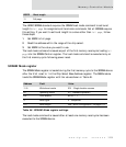
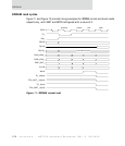
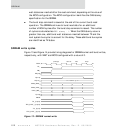
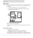
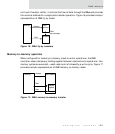
SDRAM write cycles
Figure 13 and Figure 14 provide timing diagrams for SDRAM normal and burst writes,
respectively, with WAIT and BCYC configured with a value of 0.
Figure 13: SDRAM normal write
One Valid Per Cycle
precharge activate write bstop
BCLK
TS_
RW_
BE[3:0]
D[31:0]
CS[7:0]_
CAS3_(RAS_)
CAS2_(CAS_)
CAS1_(WE_)
A[13:0]
AMUX
TA_ {output}
TEA_(LAST_) {output}
TA_ {input}
TEA_(LAST_) {input}