


www.digi.com
269
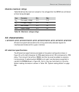
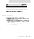
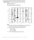
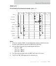
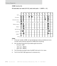
Electrical Characteristics
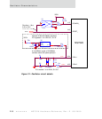
Timing Diagrams
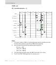
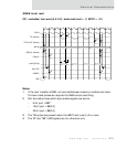
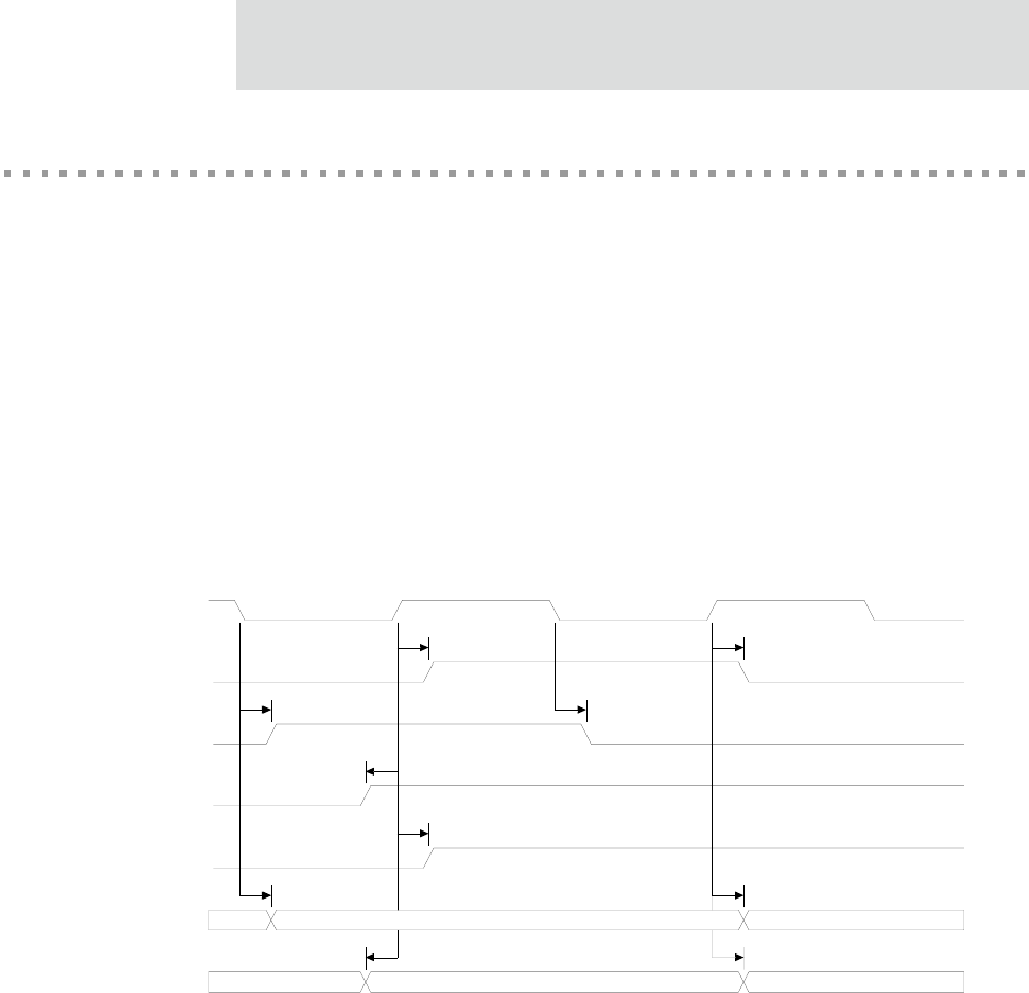
Timing_Specifications
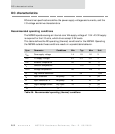
All timing specifications consist of the relationship between a reference clock and a
signal:
There are bussed and non–bussed signals. Non–bussed signals separately
illustrate 0–to–1 and 1–to–0 transitions.
Inputs have setup/hold times versus clock rising.
Outputs have switching time relative to either clock rising or clock falling.
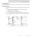
Note:
Timing relationships in this diagram are drawn without proportion to actual
delay.
HoldSetup time
Valid from rising edgeValid from falling edge
Hold time
Setup time
1-to-0 from falling edge0-to-1 from falling edge
1-to-0 from rising edge0-to-1 from rising edge
Clock
Signal
Bus