


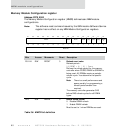

MEM module configuration
98
NS7520 Hardware Reference, Rev. D 03/2006
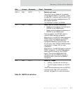
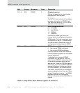
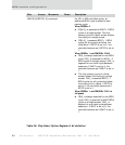
WAIT[3:0]/BCYC[1:0] continued For OE- or WE-controlled cycles, an
additional BCLK cycle is added to each
memory cycle.
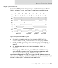
When DRSEL=0
CS[4:0]_ is asserted for WAIT+2 BCLK
cycles in a single access. The first
memory cycle of a burst access follows
the timing of a single access.
CS[4:0]_ is asserted BCYC+1 BCLK
cycles for all cycles that follow the
initial burst. If BCYC is set to 0, the
controller behaves as if BCYC is set to
1.
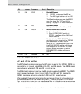
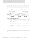
When DRSEL=1 and DMODE=2’b00
RAS_ is always asserted for one BCLK
cycle. CAS_ is asserted for WAIT+.5
BCLK cycles in a single access. CAS_ is
negated for one clock cycle between
assertions.If WAIT is set to 0, the
controller behaves as if WAIT is set to
1.
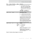
The first memory cycle of a burst
access follows the timing of a single
access. CAS_ is asserted BCYC+1
BCLK cycles for all cycles that follow
the initial cycle in a burst. If BCYC is
set to 0, the controller behaves as if
BCYC is set to 1.
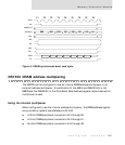
When DRSEL=1 and DMODE=2’b01 at
full speed
RAS_ is always asserted for one BCLK
cycle. CAS_ is asserted for WAIT BCLK
cycles in a single access. CAS_ is
bigoted for one clock cycle between
assertions. If WAIT is set to 0, the
controller behaves as if WAIT is set to
1.
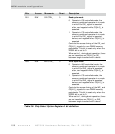
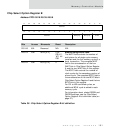
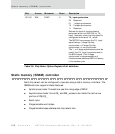
Bits Access Mnemonic Reset Description
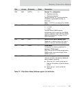
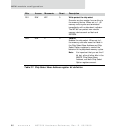
Table 38: Chip Select Option Register A bit definition