


DMA buffer descriptor
130
NS7520 Hardware Reference, Rev. D 03/2006
DMA buffer descriptor
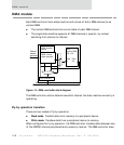
All DMA channels operate using a buffer descriptor. Each DMA channel remains idle
until enabled using the CE bit in the DMA Control register (see "DMA Control register,"
beginning on page 136). When started, a DMA channel reads the DMA buffer
descriptor pointed to by the Buffer Descriptor Pointer register (see "Buffer Descriptor
Pointer register," beginning on page 136). When the current descriptor is completed,
the next descriptor is accessed from a circular buffer.
Each DMA buffer descriptor requires two 32-bit words for fly-by mode and three 32-
bit words stored on four-word boundaries for memory-to-memory operations.
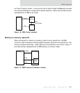
Multiple buffer descriptors are located in 1024-byte circular buffers. The first buffer
descriptor address is provided by the DMA channel’s buffer descriptor pointer.
Subsequent buffer descriptors follow the first descriptor. The final buffer descriptor
is defined with its W (wrap) bit set. When the DMA channel encounters the W bit, the
channel wraps around to the first descriptor. If the DMA channel does not encounter a
descriptor with the W bit set, the channel wraps at the 1024-byte address boundary.
Each DMA channel can address a maximum of 128 fly-by or 64 memory-to-memory
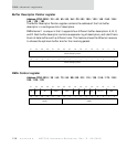
buffer descriptors. Figure 18 and Figure 19 show each descriptor type.
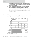
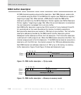
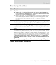
Figure 18: DMA buffer descriptor — Fly-by mode
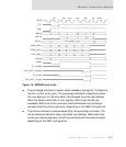
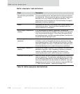
Figure 19: DMA buffer descriptor — Memory-to-memory mode
Status
Buffer pointer
Buffer length
WI L
F
31 30 29
28
16 15 0
Offset + 0
Offset + 4
Status
Source buffer pointer
Buffer length
WI L
F
31 30 29
28
16 15 0
Offset + 0
Offset + 4
Offset + 8
Offset + C
Destination buffer pointer
Reserved