


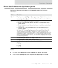
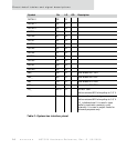

Pinout detail tables and signal descriptions
14
NS7520 Hardware Reference, Rev. D 03/2006
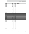
DATA12 G2 I/O 4
DATA11 F4 I/O 4
DATA10 F2 I/O 4
DATA9 F3 I/O 4
DATA8 E1 I/O 4
DATA7 E2 I/O 4
DATA6 E3 I/O 4
DATA5 D1 I/O 4
DATA4 C1 I/O 4
DATA3 B1 I/O 4
DATA2 D4 I/O 4
DATA1 D3 I/O 4
DATA0 C2 I/O 4
BE3_ D9 I/O 2 Byte enable D31:D24
BE2_ A9 I/O 2 Byte enable D23:D16
BE1_ C9 I/O 2 Byte enable D15:D08
BE0_ B9 I/O 2 Byte enable D07:D00
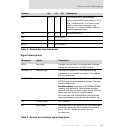
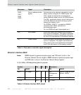
TS_ A8 U I/O 4 DO NOT USE
Add an external 820 ohm pullup to 3.3 V.
TA_ D8 U I/O 4 Data transfer acknowledge
Add an external 820 ohm pullup to 3.3 V.
TA_ is bidirectional. It is used in input
mode to terminate a memory cycle
externally. It is used in output mode for
reference purposes only.
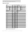
Symbol Pin I/O OD Description
Table 2: System bus interface pinout