


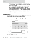


Peripheral page burst size
124
NS7520 Hardware Reference, Rev. D 03/2006
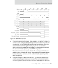
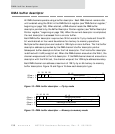
The write command is always issued during the T2 state since data is
available only at that time. If the precharge and active commands are not
required, a NOP is inserted in the T1 state of the write cycle.
Peripheral page burst size
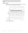
Note:
This section applies only to internal TA and TEA.
The peripheral device must provide a minimum burst page size of 64 bytes in order
for the NS7520 to support bursting to or from a memory peripheral device.
The NS7520 can begin a burst memory access on any address boundary. The NS7520
continues the burst until one of the following conditions is met:
The current bus master terminates the burst.
The memory controller terminates the burst because the number of bus
cycles for the burst cycle reached the maximum as defined in the BSIZE
field of the Chip Select Option register.
The current memory address has reached a 64-byte page boundary.
The bus master can decide to terminate the burst at any time. The memory
controller limits the maximum number of bus cycles that can occur using the BSIZE
field. The memory controller also terminates the burst when a 64-byte page
boundary is encountered.
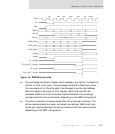
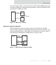
Example
The memory peripheral is configured as a 32-bit peripheral.
The memory peripheral has a 16-byte page size.
The BSIZE field is set to the maximum value 11, which implies a maximum of
16 bus cycles for each burst.
The bus master begins a 16-byte burst cycle starting with an address offset
of
’hC.