


Timing Diagrams
284
NS7520 Hardware Reference, Rev. D 03/2006
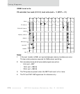
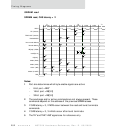
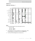
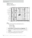
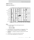
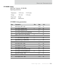
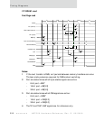
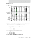
SDRAM burst read
SDRAM read, CAS latency = 2
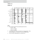
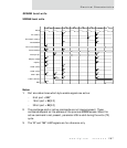
Notes:
1 Port size determines which byte enable signals are active:
– 8-bit port = BE3*
– 16-bit port = BE[3:2]
– 32-bit port = BE[3:0]
2 The precharge and/or active commands are not always present. These
commands depend on the address of the previous SDRAM access.
3 If CAS latency = 3, 5 NOPs occur between the read and burst terminate
commands.
4 If CAS latency = 3, 3 inhibits occur after burst terminate.
5 The TA* and TEA*/LAST signals are for reference only.
T1 T2 T2 T2 T2 T1
prechg active read nop nop nop nop bterm inhibit inhibit
12
343434
34343434
3434
3434
2727
3636
3535
6
3737
3131
3030
11
10
A10
BCLK
TA* (Note-5)
TEA*/LAST* (Note-5)
PortA2/AMUX
Non-muxed address
Muxed address
BE*[3:0]* (DQM)
read D[31:0]
CS[4:0]*
CAS3* (RAS)
CAS2* (CAS)
CAS1* (WE)
CAS0* (A10/AP)
RW*