


ARM INSTRUCTION SET S3C2410A
3-20
RESERVED BITS
Only twelve bits of the PSR are defined in ARM920T (N,Z,C,V,I,F, T & M[4:0]); the remaining bits are reserved for use
in future versions of the processor. Refer to Figure 2-6 for a full description of the PSR bits.
To ensure the maximum compatibility between ARM920T programs and future processors, the following rules should
be observed:
• The reserved bits should be preserved when changing the value in a PSR.
• Programs should not rely on specific values from the reserved bits when checking the PSR status, since they
may read as one or zero in future processors.
A read-modify-write strategy should therefore be used when altering the control bits of any PSR register; this involves
transferring the appropriate PSR register to a general register using the MRS instruction, changing only the relevant
bits and then transferring the modified value back to the PSR register using the MSR instruction.
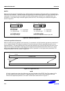
EXAMPLES
The following sequence performs a mode change:
MRS R0,CPSR ; Take a copy of the CPSR.
BIC R0,R0,#0x1F ; Clear the mode bits.
ORR R0,R0,#new_mode ; Select new mode
MSR CPSR,R0 ; Write back the modified CPSR.
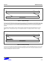
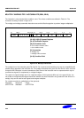
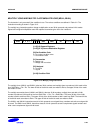
When the aim is simply to change the condition code flags in a PSR, a value can be written directly to the flag bits
without disturbing the control bits. The following instruction sets the N,Z,C and V flags:
MSR CPSR_flg,#0xF0000000 ; Set all the flags regardless of their previous state
; (does not affect any control bits).
No attempt should be made to write an 8-bit immediate value into the whole PSR since such an operation cannot
preserve the reserved bits.
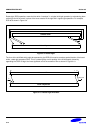
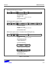
INSTRUCTION CYCLE TIMES
PSR transfers take 1S incremental cycles, where S is defined as Sequential (S-cycle).