


S3C2410A USB DEVICE
13-15
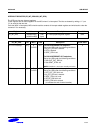
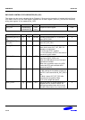
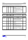
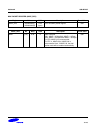
END POINT IN CONTROL STATUS REGISTER (IN_CSR1_REG/IN_CSR2_REG) (Continued)
IN_CSR1_REG Bit MCU USB Description Initial State
IN_PKT_RDY [0] R/SET CLEAR Set by the MCU after writing a packet of data
into the FIFO.
The USB clears this bit once the packet has
been successfully sent to the host.
An interrupt is generated when the USB clears
this bit, so the MCU can load the next packet.
While this bit is set, the MCU will not be able
to write to the FIFO.
If the MCU sets SEND STALL bit, this bit
cannot be set.
0
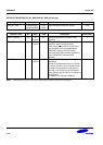
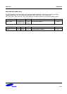
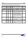
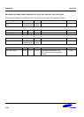
Register Address R/W Description Reset Value
IN_CSR2_REG 0x52000188(L)
0x5200018B(B)
R/W
(byte)
IN END POINT control status register2 0x20
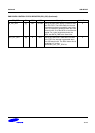
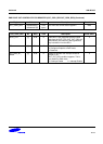
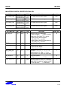
IN_CSR2_REG Bit MCU USB Description Initial State
AUTO_SET [7] R/W R If set, whenever the MCU writes MAXP data,
IN_PKT_RDY will automatically be set by the
core without any intervention from MCU.
If the MCU writes less than MAXP data,
IN_PKT_RDY bit has to be set by the MCU.
0
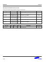
ISO [6] R/W R Used only for endpoints whose transfer type is
programmable.
1: Reserved
0: Configures endpoint to Bulk mode
0
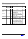
MODE_IN [5] R/W R Used only for endpoints whose direction is
programmable.
1: Configures Endpoint Direction as IN
0: Configures Endpoint Direction as OUT
1
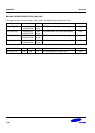
IN_DMA_INT_EN [4] R/W R Determine whether the interrupt should be
issued or not, when the IN_PKT_RDY
condition happens. This is only useful for DMA
mode.
0 = Interrupt enable, 1 = Interrupt Disable
0
Reserved [3:0] – – – –