


S3C2410A UART
11-7
Baud-Rate Generation
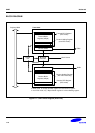
Each UART's baud-rate generator provides the serial clock for the transmitter and the receiver. The source clock for
the baud-rate generator can be selected with the S3C2410A's internal system clock or UEXTCLK. In other words,
dividend is selectable by setting Clock Selection of UCONn. The baud-rate clock is generated by dividing the source
clock (PCLK or UEXTCLK) by 16 and a 16-bit divisor specified in the UART baud-rate divisor register (UBRDIVn). The
UBRDIVn can be determined by the following expression:
UBRDIVn = (int)(PCLK/(bps x 16) ) -1
Where, the divisor should be from 1 to (2
16
-1).
For accurate UART operation, the S3C2410A also supports UEXTCLK as a dividend.
If the S3C2410A uses UEXTCLK, which is supplied by an external UART device or system, then the serial clock of
UART is exactly synchronized with UEXTCLK. So, the user can get the more precise UART operation. The UBRDIVn
can be determined:
UBRDIVn = (int)(UEXTCLK / (bps x 16) ) –1
Where, the divisor should be from 1 to (2
16
-1) and UEXTCLK should be smaller than PCLK.
For example, if the baud-rate is 115200 bps and PCLK or UEXTCLK is 40 MHz, UBRDIVn is determined:
UBRDIVn = (int)(40000000/(115200 x 16)) -1
= (int)(21.7) -1
= 21 -1 = 20
Baud-Rate Error Tolerance
UART Frame error should be less than 1.87%(3/160).
tUPCLK = (UBRDIVn + 1) x 16 x 1Frame / PCLK tUPCLK : Real UART Clock
tUEXACT = 1Frame / baud-rate tUEXACT : Ideal UART Clock
UART error = (tUPCLK – tUEXACT) / tUEXACT x 100%
NOTES
1. 1Frame = start bit + data bit + parity bit + stop bit.
2. In specific condition, we can support baud rate up to 921.6K bps. For example, when PCLK is 60MHz,
you can use baud rate of 921.6K bps under UART error of 1.69%.
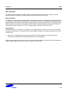
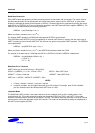
Loopback Mode
The S3C2410A UART provides a test mode referred to as the Loopback mode, to aid in isolating faults in the
communication link. This mode structurally enables the connection of RXD and TXD in the UART. In this mode,
therefore, transmitted data is received to the receiver, via RXD. This feature allows the processor to verify the internal
transmit and to receive the data path of each SIO channel. This mode can be selected by setting the loopback bit in
the UART control register (UCONn).