


ARM INSTRUCTION SET S3C2410A
3-12
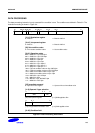
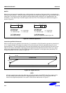
SHIFTS
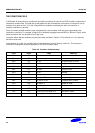
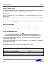
When the second operand is specified to be a shifted register, the operation of the barrel shifter is controlled by the
Shift field in the instruction. This field indicates the type of shift to be performed (logical left or right, arithmetic right or
rotate right). The amount by which the register should be shifted may be contained in an immediate field in the
instruction, or in the bottom byte of another register (other than R15). The encoding for the different shift types is
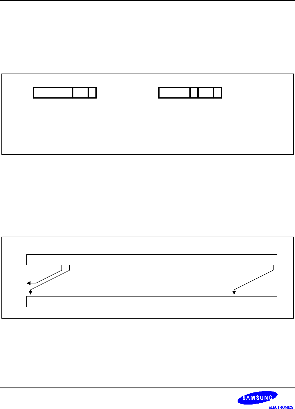
shown in Figure 3-5.
0
[6:5] Shift type
00 = logical left 01 = logical right
10 = arithmetic right 11 = rotate right
[11:7] Shift amount
5 bit unsigned integer
[6:5] Shift type
00 = logical left 01 = logical right
10 = arithmetic right 11 = rotate right
[11:8] Shift register
Shift amount specified in bottom-byte of Rs
456711
1
456711 8
0RS
Figure 3-5. ARM Shift Operations
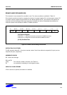
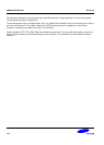
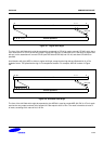
Instruction specified shift amount
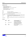
When the shift amount is specified in the instruction, it is contained in a 5-bit field which may take any value from 0
to 31. A logical shift left (LSL) takes the contents of Rm and moves each bit by the specified amount to a more
significant position. The least significant bits of the result are filled with zeros, and the high bits of Rm which do not
map into the result are discarded, except that the least significant discarded bit becomes the shifter carry output
which may be latched into the C bit of the CPSR when the ALU operation is in the logical class (see above). For
example, the effect of LSL #5 is shown in Figure 3-6.
31 27 26
Contents of Rm
Value of Operand 2
carry out
0
0
0000
Figure 3-6. Logical Shift Left
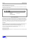
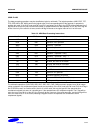
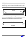
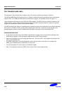
NOTE
LSL #0 is a special case, where the shifter carry out is the old value of the CPSR C flag. The contents of Rm
are used directly as the second operand. A logical shift right (LSR) is similar, but the contents of Rm are
moved to less significant positions in the result. LSR #5 has the effect shown in Figure 3-7.