


S3C2410A SPI INTERFACE
22-9
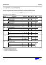
SPI PIN CONTROL REGISTER
When the SPI system is enabled, the direction of pins, except nSS pin, is controlled by MSTR bit of SPCONn
register. The direction of nSS pin is always input.
When the SPI is a master, nSS pin is used to check multi-master error, provided the SPPIN's ENMUL bit is active,
and another GPIO should be used to select a slave.
If the SPI is configured as a slave, the nSS pin is used to select SPI as a slave by one master.
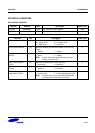
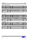
Register Address R/W Description Reset Value
SPPIN0 0x59000008 R/W SPI channel 0 pin control register 0x02
SPPIN1 0x59000028 R/W SPI channel 1 pin control register 0x02
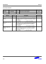
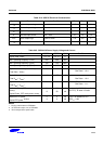
SPPINn Bit Description Initial State
Reserved [7:3]
Multi Master error detect
Enable (ENMUL)
[2] The /SS pin is used as an input to detect multi master error
when the SPI system is a master.
0 = disable (general purpose)
1 = multi master error detect enable
0
Reserved [1] This bit should be "1". 1
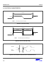
Master Out Keep (KEEP) [0] Determine MOSI drive or release when 1byte transmit is
completed (only master).
0 = release, 1 = drive the previous level
0
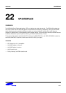
The SPIMISO (MISO) and SPIMOSI (MOSI) data pins are used for transmitting and receiving serial data. When the
SPI is configured as a master, SPIMISO (MISO) is the master data input line, SPIMOSI (MOSI) is the master data
output line, and SPICLK (SCK) is the clock output line. When the SPI becomes a slave, these pins perform reversed
roles. In a multiple-master system, SPICLK (SCK) pins, SPIMOSI (MOSI) pins, and SPIMISO (MISO) pins are tied
to configure a group respectively.
A master SPI can experience a multi master error, when other SPI device working as a master selects the S3C2410
SPI as a slave. When this error is detected, the following actions are taken immediately. But you must previously set
SPPINn's ENMUL bit if you want to detect this error.
1. The SPCONn's MSTR bit is forced to 0 to operate slave mode.
2. The SPSTAn's MULF flag is set, and an SPI interrupt is generated.