


ARM INSTRUCTION SET S3C2410A
3-54
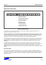
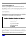
THE COPROCESSOR FIELDS
The CP# field is used to identify the coprocessor which is required to supply or accept the data, and a coprocessor
will only respond if its number matches the contents of this field.
The CRd field and the N bit contain information for the coprocessor which may be interpreted in different ways by
different coprocessors, but by convention CRd is the register to be transferred (or the first register where more than
one is to be transferred), and the N bit is used to choose one of two transfer length options. For instance N=0 could
select the transfer of a single register, and N = 1 could select the transfer of all the registers for context switching.
ADDRESSING MODES
ARM920T is responsible for providing the address used by the memory system for the transfer, and the addressing
modes available are a subset of those used in single data transfer instructions. Note, however, that the immediate
offsets are 8 bits wide and specify word offsets for coprocessor data transfers, whereas they are 12 bits wide and
specify byte offsets for single data transfers.
The 8-bit unsigned immediate offset is shifted left 2 bits and either added to (U = 1) or subtracted from (U = 0) the
base register (Rn); this calculation may be performed either before (P = 1) or after (P = 0) the base is used as the
transfer address. The modified base value may be overwritten back into the base register (if W = 1), or the old value
of the base may be preserved (W = 0). Note that post-indexed addressing modes require explicit setting of the W bit,
unlike LDR and STR which always write-back when post-indexed.
The value of the base register, modified by the offset in a pre-indexed instruction, is used as the address for the
transfer of the first word. The second word (if more than one is transferred) will go to or come from an address one
word (4 bytes) higher than the first transfer, and the address will be incremented by one word for each subsequent
transfer.
ADDRESS ALIGNMENT
The base address should normally be a word aligned quantity. The bottom 2 bits of the address will appear on A[1:0]
and might be interpreted by the memory system.
Use of R15
If Rn is R15, the value used will be the address of the instruction plus 8 bytes. Base write-back to R15 must not be
specified.
DATA ABORTS
If the address is legal but the memory manager generates an abort, the data trap will be taken. The write-back of the
modified base will take place, but all other processor state will be preserved. The coprocessor is partly responsible
for ensuring that the data transfer can be restarted after the cause of the abort has been resolved, and must ensure
that any subsequent actions it undertakes can be repeated when the instruction is retried.
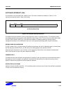
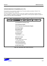
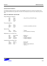
Instruction cycle times
Coprocessor data transfer instructions take (n-1)S + 2N + bI incremental cycles to execute, where:
n The number of words transferred.
b The number of cycles spent in the coprocessor busy-wait loop.
S, N and I are defined as sequential (S-cycle), non-sequential (N-cycle), and internal (I-cycle), respectively.