


S3C2410A UART
11-5
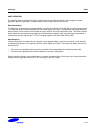
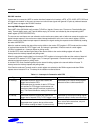
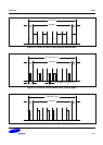
RS-232C interface
If users want to connect the UART to modem interface (instead of null modem), nRTS, nCTS, nDSR, nDTR, DCD and
nRI signals are needed. In this case, the users can control these signals with general I/O ports by software because
the AFC does not support the RS-232C interface.
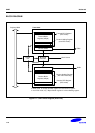
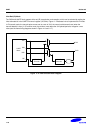
Interrupt/DMA Request Generation
Each UART of the S3C2410A has five status (Tx/Rx/Error) signals: Overrun error, Frame error, Receive buffer data
ready, Transmit buffer empty, and Transmit shifter empty, all of which are indicated by the corresponding UART
status register (UTRSTATn/UERSTATn).
The overrun error and frame error are referred to as the receive error status, each of which can cause the receive error
status interrupt request, if the receive-error-status-interrupt-enable bit is set to one in the control register, UCONn.
When a receive-error-status-interrupt-request is detected, the signal causing the request can be identified by reading
the value of UERSTSTn.
When the receiver transfers the data of the receive shifter to the receive FIFO register in FIFO mode and the number
of received data reaches Rx FIFO Trigger Level, Rx interrupt is generated, if Receive mode in control register
(UCONn) is selected as 1 (Interrupt request or polling mode).
In the Non-FIFO mode, transferring the data of the receive shifter to the receive holding register will cause Rx
interrupt under the Interrupt request and polling mode.
When the transmitter transfers data from its transmit FIFO register to its transmit shifter and the number of data left
in transmit FIFO reaches Tx FIFO Trigger Level, Tx interrupt is generated, if Transmit mode in control register is
selected as Interrupt request or polling mode.
In the Non-FIFO mode, transferring data from the transmit holding register to the transmit shifter will cause Tx
interrupt under the Interrupt request and polling mode.
If the Receive mode and Transmit mode in control register are selected as the DMAn request mode then DMAn
request occurs instead of Rx or Tx interrupt in the situation mentioned above.
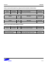
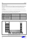
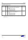
Table 11-1. Interrupts in Connection with FIFO
Type FIFO Mode Non-FIFO Mode
Rx interrupt Generated whenever receive data reaches the
trigger level of receive FIFO.
Generated when the number of data in FIFO does
not reaches Rx FIFO trigger Level and does not
receive any data during 3 word time (receive time
out). This interval follows the setting of Word Length
bit.
Generated by the receive holding register
whenever receive buffer becomes full.
Tx interrupt Generated whenever transmit data reaches the
trigger level of transmit FIFO (Tx FIFO trigger Level).
Generated by the transmit holding register
whenever transmit buffer becomes empty.
Error interrupt Generated when frame error has detected.
Generated when it gets to the top of the receive
FIFO without reading out data in it (overrun error).
Generated by all errors. However if another
error occurs at the same time, only one
interrupt is generated.