


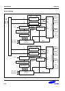

S3C2410A IIS-BUS INTERFACE
21-3
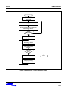
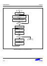
DMA Transfer
In this mode, transmit or receive FIFO is accessible by the DMA controller. DMA service request in transmit or
receive mode is made by the FIFO ready flag automatically.
Transmit and Receive Mode
In this mode, IIS bus interface can transmit and receive data simultaneously.
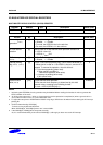
AUDIO SERIAL INTERFACE FORMAT
IIS-BUS FORMAT
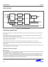
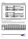
The IIS bus has four lines including serial data input (IISDI), serial data output (IISDO), left/right channel select
(IISLRCK), and serial bit clock (IISCLK); the device generating IISLRCK and IISCLK is the master.
Serial data is transmitted in 2's complement with the MSB first. The MSB is transmitted first because the transmitter
and receiver may have different word lengths. The transmitter does not have to know how many bits the receiver can
handle, nor does the receiver need to know how many bits are being transmitted.
When the system word length is greater than the transmitter word length, the word is truncated (least significant data
bits are set to '0') for data transmission. If the receiver gets more bits than its word length, the bits after the LSB are
ignored. On the other hand, if the receiver gets fewer bits than its word length, the missing bits are set to zero
internally. And therefore, the MSB has a fixed position, whereas the position of the LSB depends on the word length.
The transmitter sends the MSB of the next word at one clock period whenever the IISLRCK is changed.
Serial data sent by the transmitter may be synchronized with either the trailing (HIGH to LOW) or the leading (LOW
to HIGH) edge of the clock signal. However, the serial data must be latched into the receiver on the leading edge of
the serial clock signal, and so there are some restrictions when transmitting data that is synchronized with the
leading edge.
The LR channel select line indicates the channel being transmitted. IISLRCK may be changed either on a trailing or
leading edge of the serial clock, but it does not need to be symmetrical. In the slave, this signal is latched on the
leading edge of the clock signal. The IISLRCK line changes one clock period before the MSB is transmitted. This
allows the slave transmitter to derive synchronous timing of the serial data that will be set up for transmission.
Furthermore, it enables the receiver to store the previous word and clear the input for the next word.
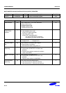
MSB (LEFT) JUSTIFIED
MSB / left justified bus format is the same as IIS bus format architecturally. Only, different from the IIS bus format,
the MSB justified format realizes that the transmitter always sends the MSB of the next word whenever the IISLRCK
is changed.