


S3C2410A THUMB INSTRUCTION SET
4-13
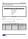
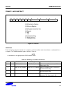
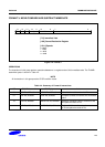
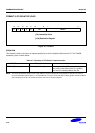
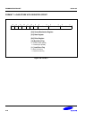
FORMAT 5: HI-REGISTER OPERATIONS/BRANCH EXCHANGE
15 0
0
14
10
[2:0] Destination Register
[5:3] Source Register
[6] Hi Operand Flag 2
[7] Hi Operand Flag 1
[9:8] Opcode
6 5
3 2
Rd/Hd0 0
13 12
11
Op Rs/Hs0 0 0
9 8 7
H1 H2
Figure 4-6. Format 5
OPERATION
There are four sets of instructions in this group. The first three allow ADD, CMP and MOV operations to be performed
between Lo and Hi registers, or a pair of Hi registers. The fourth, BX, allows a Branch to be performed which may
also be used to switch processor state. The THUMB assembler syntax is shown in Table 4-6.
NOTE
In this group only CMP (Op = 01) sets the CPSR condition codes.
The action of H1= 0, H2 = 0 for Op = 00 (ADD), Op =01 (CMP) and Op = 10 (MOV) is undefined, and should not be
used.
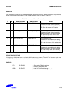
Table 4-6. Summary of Format 5 Instructions
Op H1 H2 THUMB assembler ARM equivalent Action
00 0 1 ADD Rd, Hs ADD Rd, Rd, Hs Add a register in the range 8-15 to a
register in the range 0-7.
00 1 0 ADD Hd, Rs ADD Hd, Hd, Rs Add a register in the range 0-7 to a
register in the range 8-15.
00 1 1 ADD Hd, Hs ADD Hd, Hd, Hs Add two registers in the range 8-15
01 0 1 CMP Rd, Hs CMP Rd, Hs Compare a register in the range 0-7
with a register in the range 8-15. Set
the condition code flags on the result.
01 1 0 CMP Hd, Rs CMP Hd, Rs Compare a register in the range 8-15
with a register in the range 0-7. Set the
condition code flags on the result.