


UART S3C2410A
11-10
UART SPECIAL REGISTERS
UART LINE CONTROL REGISTER
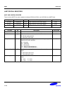
There are three UART line control registers including ULCON0, ULCON1, and ULCON2 in the UART block.
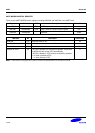
Register Address R/W Description Reset Value
ULCON0 0x50000000 R/W UART channel 0 line control register 0x00
ULCON1 0x50004000 R/W UART channel 1 line control register 0x00
ULCON2 0x50008000 R/W UART channel 2 line control register 0x00
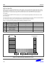
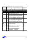
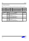
ULCONn Bit Description Initial State
Reserved [7] 0
Infra-Red Mode [6] Determine whether or not to use the Infra-Red mode.
0 = Normal mode operation
1 = Infra-Red Tx/Rx mode
0
Parity Mode [5:3] Specify the type of parity generation and checking during UART
transmit and receive operation.
0xx = No parity
100 = Odd parity
101 = Even parity
110 = Parity forced/checked as 1
111 = Parity forced/checked as 0
000
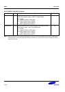
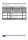
Number of Stop Bit [2] Specify how many stop bits are to be used for end-of-frame
signal.
0 = One stop bit per frame
1 = Two stop bit per frame
0
Word Length [1:0] Indicate the number of data bits to be transmitted or received per
frame.
00 = 5-bit 01 = 6-bit
10 = 7-bit 11 = 8-bit
00