


S3C2410A USB DEVICE
13-21
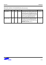
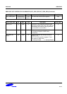
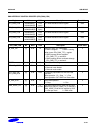
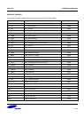
DMA INTERFACE CONTROL REGISTER (EPN_DMA_CON)
Register Address R/W Description Reset Value
EP1_DMA_CON 0x52000200(L)
0x52000203(B)
R/W
(byte)
EP1 DMA interface control register 0x00
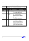
EP2_DMA_CON 0x52000218(L)
0x5200021B(B)
R/W
(byte)
EP2 DMA interface control register 0x00
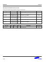
EP3_DMA_CON 0x52000240(L)
0x52000243(B)
R/W
(byte)
EP3 DMA interface control register 0x00
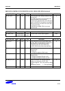
EP4_DMA_CON 0x52000258(L)
0x5200025B(B)
R/W
(byte)
EP4 DMA interface control register 0x00
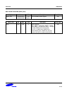
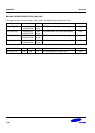
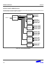
EPn_DMA_CON Bit MCU USB Description Initial State
IN_RUN_OB [7] R/W W Read) IN_DMA_Run Observation
0: DMA is stopped 1:DMA is running
Write) Ignore EPn_DMA_TTC_n register
0: DMA requests will be stopped if
EPn_DMA_TTC_n reaches 0.
1: DMA requests will be continued although
EPn_DMA_TTC_n reaches 0.
0
STATE [6:4] R W DMA State Monitoring 0
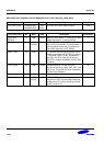
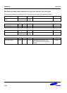
DEMAND_MODE [3] R/W R DMA Demand mode enable bit
0: Demand mode disable
1: Demand mode enable
0
OUT_RUN_OB/
OUT_DMA_RUN
[2] R/W R/W Functionally separated into write and read
operation.
Write operation: "0" = Stop "1" = Run
Read operation: OUT DMA Run Observation
0
IN_DMA_RUN [1] R/W R Start DMA operation.
0 = Stop 1 = Run
0
DMA_MODE_EN [0] R/W R/
CLEAR
Set DMA mode.If the IN_RUN_OB has been
wrtten as 0 and EPn_DMA_TTC_n reaches 0,
DMA_MODE_EN bit will be cleared by USB.
0 = Interrupt mode 1 = DMA mode
0