


ARM920T PROCESSOR CACHES, WRITE BUFFER
4-1
Appendix 4
CACHES, WRITE BUFFER
ABOUT THE CACHES AND WRITE BUFFER
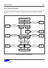
The ARM920T includes an instruction cache, a data cache, a write buffer and a Physical Address TAG RAM to
reduce the effect of main memory bandwidth and latency on performance.
• The ARM920T implements separate 16KB instruction and 16KB data caches.
• The caches have the following features:
• Virtually-addressed 64-way associative cache.
• 8 words per line (32 bytes per line) with one valid bit and two dirty bits per line, allowing half-line write-backs.
• Write-through and write-back cache operation (write-back caches are also known as copy back caches),
selected per memory region by the C and B bits in the MMU translation tables (for data cache only).
• Pseudo-random or round-robin replacement, selectable via RR bit in CP15 register 1.
• Low-power CAM-RAM implementation.
• Caches independently lockable with granularity of 1/64th of cache, which is 64 words (256 bytes).
• For compatibility with Microsoft WindowsCE, and to reduce interrupt latency, the physical address
corresponding to each data cache entry is stored in the physical address TAG RAM for use during cache line
write-backs, in addition to the virtual address TAG stored in the cache CAMs. This means that the MMU is not
involved in cache write-back operations, removing the possibility of TLB misses related to the write-back
address.
• Cache maintenance operations to provide efficient cleaning of the entire data cache, and to provide efficient
cleaning and invalidation of small regions of virtual memory. The latter allows ICache coherency to be efficiently
maintained when small code changes occur, for example self-modifying code and changes to exception vectors.
The write buffer can hold 16 words of data and four addresses.