


LCD CONTROLLER S3C2410A
15-30
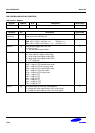
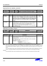
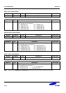
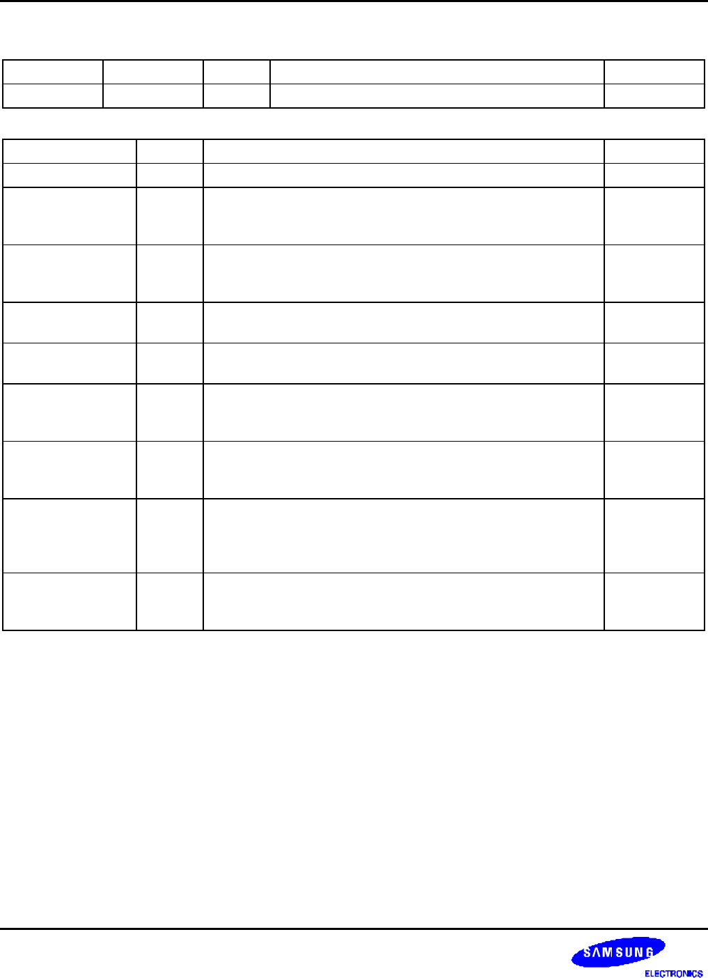
LCD Control 5 Register
Register Address R/W Description Reset Value
LCDCON5 0X4D000010 R/W LCD control 5 register 0x00000000
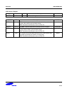
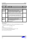
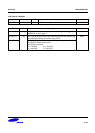
LCDCON5 Bit Description Initial state
Reserved [31:17] This bit is reserved and the value should be '0'. 0
VSTATUS [16:15] TFT: Vertical Status (read only).
00 = VSYNC 01 = BACK Porch
10 = ACTIVE 11 = FRONT Porch
00
HSTATUS [14:13] TFT: Horizontal Status (read only).
00 = HSYNC 01 = BACK Porch
10 = ACTIVE 11 = FRONT Porch
00
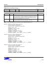
BPP24BL [12] TFT: This bit determines the order of 24 bpp video memory.
0 = LSB valid 1 = MSB Valid
0
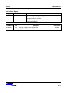
FRM565 [11] TFT: This bit selects the format of 16 bpp output video data.
0 = 5:5:5:1 Format 1 = 5:6:5 Format
0
INVVCLK [10] STN/TFT: This bit controls the polarity of the VCLK active edge.
0 = The video data is fetched at VCLK falling edge
1 = The video data is fetched at VCLK rising edge
0
INVVLINE [9] STN/TFT: This bit indicates the VLINE/HSYNC pulse polarity.
0 = Normal
1 = Inverted
0
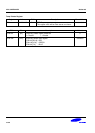
INVVFRAME [8] STN/TFT: This bit indicates the VFRAME/VSYNC pulse
polarity.
0 = Normal
1 = Inverted
0
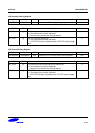
INVVD [7] STN/TFT: This bit indicates the VD (video data) pulse polarity.
0 = Normal
1 = VD is inverted.
0