


S3C2410A DMA
8-7
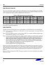
DMA SPECIAL REGISTERS
Each DMA channel has nine control registers (36 in total since there are four channels for DMA controller). Six of the
control registers control the DMA transfer, and other three ones monitor the status of DMA controller. The details of
those registers are as follows.
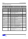
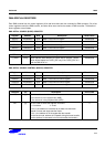
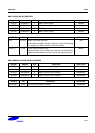
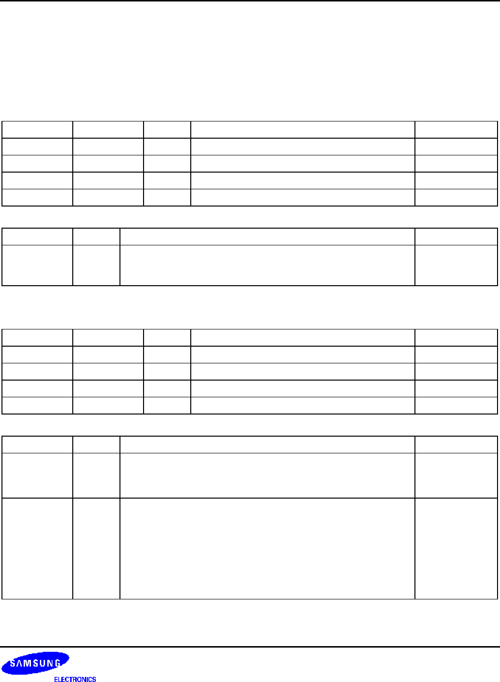
DMA INITIAL SOURCE (DISRC) REGISTER
Register Address R/W Description Reset Value
DISRC0 0x4B000000 R/W DMA 0 initial source register 0x00000000
DISRC1 0x4B000040 R/W DMA 1 initial source register 0x00000000
DISRC2 0x4B000080 R/W DMA 2 initial source register 0x00000000
DISRC3 0x4B0000C0 R/W DMA 3 initial source register 0x00000000
DISRCn Bit Description Initial State
S_ADDR [30:0] Base address (start address) of source data to transfer. This bit
value will be loaded into CURR_SRC only if the CURR_SRC is 0
and the DMA ACK is 1.
0x00000000
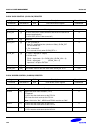
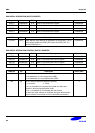
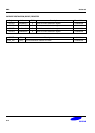
DMA INITIAL SOURCE CONTROL (DISRCC) REGISTER
Register Address R/W Description Reset Value
DISRCC0 0x4B000004 R/W DMA 0 initial source control register 0x00000000
DISRCC1 0x4B000044 R/W DMA 1 initial source control register 0x00000000
DISRCC2 0x4B000084 R/W DMA 2 initial source control register 0x00000000
DISRCC3 0x4B0000C4 R/W DMA 3 initial source control register 0x00000000
DISRCCn Bit Description Initial State
LOC [1] Bit 1 is used to select the location of source.
0: the source is in the system bus (AHB).
1: the source is in the peripheral bus (APB).
0
INC [0] Bit 0 is used to select the address increment.
0 = Increment 1= Fixed
If it is 0, the address is increased by its data size after each
transfer in burst and single transfer mode.
If it is 1, the address is not changed after the transfer.
(In the burst mode, address is increased during the burst transfer,
but the address is recovered to its first value after the transfer.)
0