


S3C2410A ARM INSTRUCTION SET
3-45
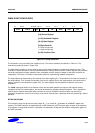
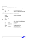
ASSEMBLER SYNTAX
<LDM|STM>{cond}<FD|ED|FA|EA|IA|IB|DA|DB> Rn{!},<Rlist>{^}
where:
{cond} Two character condition mnemonic. See Table 3-2.
Rn An expression evaluating to a valid register number
<Rlist> A list of registers and register ranges enclosed in {} (e.g. {R0,R2-R7,R10}).
{!} If present requests write-back (W = 1), otherwise W = 0.
{^} If present set S bit to load the CPSR along with the PC, or force transfer of user bank
when in privileged mode.
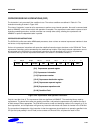
Addressing Mode Names
There are different assembler mnemonics for each of the addressing modes, depending on whether the instruction is
being used to support stacks or for other purposes. The equivalence between the names and the values of the bits in
the instruction are shown in the following table 3-6.
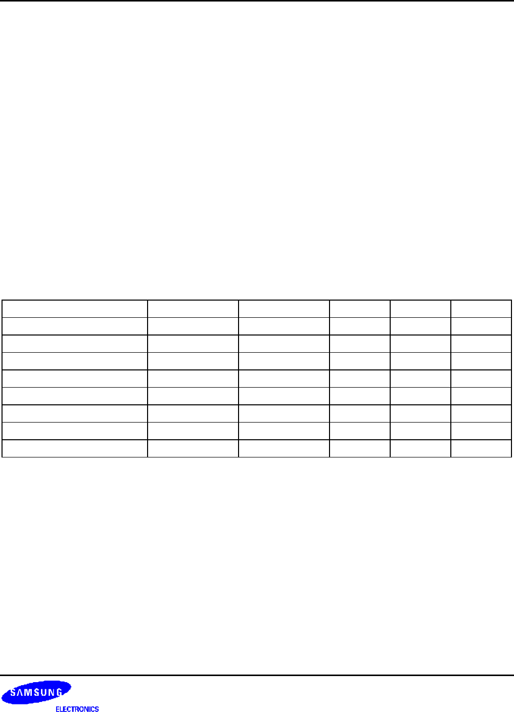
Table 3-6. Addressing Mode Names
Name Stack Other L bit P bit U bit
Pre-Increment Load LDMED LDMIB 1 1 1
Post-Increment Load LDMFD LDMIA 1 0 1
Pre-Decrement Load LDMEA LDMDB 1 1 0
Post-Decrement Load LDMFA LDMDA 1 0 0
Pre-Increment Store STMFA STMIB 0 1 1
Post-Increment Store STMEA STMIA 0 0 1
Pre-Decrement Store STMFD STMDB 0 1 0
Post-Decrement Store STMED STMDA 0 0 0
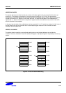
FD, ED, FA, EA define pre/post indexing and the up/down bit by reference to the form of stack required. The F and E
refer to a "full" or "empty" stack, i.e. whether a pre-index has to be done (full) before storing to the stack. The A and
D refer to whether the stack is ascending or descending. If ascending, a STM will go up and LDM down, if
descending, vice-versa.
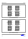
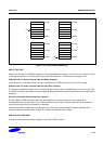
IA, IB, DA, DB allow control when LDM/STM are not being used for stacks and simply mean Increment After,
Increment Before, Decrement After, Decrement Before.